The S_MPI driver provides communication of Control Web application with SIMATIC S7 PLCs over the MPI or PROFIBUS
protocol.
Driver features
The driver enables connection of one or multiple SIMATIC
S7 PLC(s) to Control Web application. Supports communication with S7-200 and S7-300/400/M7/C7
series PLCs. Reads and writes data from/to D, V, M, A, E, T, Z,
Sareas. Enables manipulation with individual bits of the M
area.
Warning: The driver requires the Simens PRODAVE S7
product installed on the computer. List of sections: - Driver features
- The PRODAVE S7 software support
- How the driver works
- Driver parameters
- Driver channels
- Driver procedures
- Driver map file and data types
- Driver exceptions and their handling
- Error codes
- Example of driver usage
The PRODAVE S7 software support
Control Web MPI driver requires the Siemens
PRODAVE S7 (v.5.5 and higher) product is installed on the
computer. The PRODAVE is supplied in two versions. The cheaper
PRODAVE S7 mini enables data transfer to/from
S7-300/400/M7/C7 datablocks only. Only the Varea is
supported in the case of S7-200 PLC. The full version of
PRODAVE S7 supports also data transfer to/from M, A, E,
T, Zand Sareas. Appropriate hardware is also required
to communicate over the MPI interface. It is possible to use the
PCI plug-in board CP5611 or the PCMCIA adapter CP5511. It is also
possible to use external PC Adapter (MPI), which is connected to
the standard PC serial interface RS-232C. It is of course
necessary to install appropriate drivers for the used
hardware..
The Siemens PG/PC interface configuration
It is necessary to configure the PC/PC interface for the
driver to work properly. Configuration tools can be found in
the Windows Control Panel under the icon:

It is necessary to choose so-called Access Point first.
Choose the S7ONLINE from the combo-box:
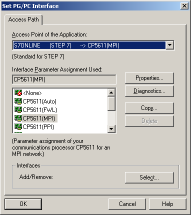
Then it is necessary to define other parameters. Select
communication hardware and MPI interface. The CP5611 card is
chosen as an example here:
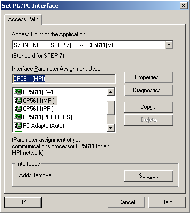
Another possibility is the PC Adapter (MPI):
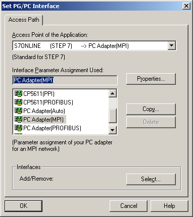
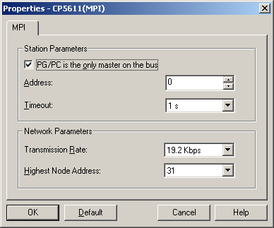
Clicking the Properties button opens dialog pox
for particular hardware. It is important to define
communication speed properly. Take care to define if the PC
(PG/PC) is the only master in the MPI network. If you use
S7-200, this option must be checked.
The S_MPI driver creates the 'ERROR.DAT' file in
the Control Web directory with error
messages. The PRODAVE S7 software creates another two
files 'ERROR.ENG' and 'ERROR.GER' with
error messages in English and German languages. The
'ERROR.DAT' file can be replaced by one of these
files, but it is necessary to keep the '.DAT'
extension.
How the driver works
It is possible to read and/or write data from/to data areas D,
V, M, A, E, T, Zand S. It is also possible to manipulate
with individual bits of the M area.
The driver automatically detects the version of PRODAVE
S7 installed on the particular computer and uses only the
functionality provided by the installed version. If the driver is
configured to use unsupported data areas, it will generate an
error during the application startup.
The driver interprets PLC'sdata elements as boolean or
numeric channels. Data element is usually a byte (in the D, V, M,
A, E and Sareas) or word (in the T and Zareas).
Numerical values can be of different types (int8,
uint8, int16, uint16,
int32, uint32, float32,
float32s), depending on the number of data elements
occupied. Also logical channels can be of different types (bits,
sbit, bool8) depending on the
interpretation (one bit or whole byte). If the whole byte is
interpreted as one logical value then zero value means false,
non-zero value means true. Driver data channels (number of
channels and their types) are configured in the driver parameter
file according to the user needs.
Driver parameters
The driver parameter file defines various communication
parameters and also individual channels. The whole parameter file
is divided into individual sections. Section name is delimited by
square brackets. Individual parameters within the section follows
the parameter_name = parameter_value convention. Every parameter
occupies exactly one line.
Connections definition — section
[Connection]
All devices (PLCs), with which the driver has to
communicate, are defined in this section. Every device has
assigned name, which identifies it in the [Channels]
section, and also device address and possibly another
parameters identifying the device are defined here. Number of
connections is limited to 32. Every connection is defined on
the separate line according to the following syntax:
[Connection]
  <Id> = station:<N>, segment:<N>, rack:<N>, slot:<N>, cpu:<N>
  <Id> = ...
  ...
Id - connection identifier, which
will be used in the [Channels] section. Id is a
character string of maximal length 32 character. N - numeric value. It can be written
in the decimal or hexadecimal notation (hexadecimal number
must begin with number and end with the character H, e.g.
0A1H).
The cpu parameter defines PLC series. The
S7-200 is identified by the number 200, Higher models
(S7-300/400/M7/C7) are identified by the number 300. It is
also possible to use short notation, where on the right side
of the equal sign are only numbers in the following orders:
station, segment, rack, slot, cpu.
Example of the [Connection] section
parameters:
[Connection]
  CPU314 = station:3, segment:0, rack:0, slot:2, cpu:300
or
CPU314 = 3, 0, 0, 2, 300
Driver parameter definition — section [Settings]
This section contains parameters, which configures the
driver. Individual parameters and their possible values
are:
[Settings]
  DeviceName = <Device>
  ErrorFile = <File>
  SwapBytes = true | false
  MaxExceptions = <N>
  FinalizeAfterEachBlock = false | true
  Trace = none | log | xtrace | windows
| Device | string (S7ONLINE). | | File | string ('ERROR.DAT'). | | N | numeric value. It can be written in the decimal or
hexadecimal notation (hexadecimal number must begin with
number and end with the character H, e.g. 0A1H). |
Individual parameters description: | DeviceName | Name of hardware driver (Access Point) — typically S7ONLINE. | | ErrorFile | Error messages file name — e.g.
'ERROR.DAT'. This file must be in the
Control Web root directory. | | SwapBytes | flag which states whether swap byte
order is altered in the word. This flag is global for all blocks. If it
is set to false or is not stated, it is possible to set swap byte order
individually within the channels blocks. | | MaxExceptions | size of the queue for unprocessed
exceptions from the driver. The default setting is 4096. | | FinalizeAfterEachBlock | using this parameter it is
stated whether data will be transferred to the application after each
communication (the value of the parameter = true) or after
completion of the transfer of all blocks which are resolved within the
respective time step. The default value is false. | | Trace | switching of communication trace outputs.
If it is necessary to monitor the communication of the driver with the
device, it is possible to select by this parameter the target of trace
outputs. Possible values of the parameter are: | none | no trace outputs | | log | outputs are directed into Log window of the tab
Debug of the Control Websystem | | xtrace | outputs are directed into the file
'\XTRACE.TXT' | | windows | outputs are directed into the debug window of the Windows
system |
Warning: Trace outputs slow down the activity of the
application or they may lead to decreasing the space in the memory or on
the disk. Therefore, it is not recommended to use trace
outputs in the final application. |
Example of the [Settings] section:
[Settings]
  DeviceName = S7ONLINE
  ErrorFile = ERROR.DAT
  SwapBytes = false
  MaxExceptions = 1000
  FinalizeAfterEachBlock = false
  Trace = none
Channels definition — section
[Channels]
This section defines individual channels or group of
channels and their representation in the PLC'smemory.
Groups are defined in individual blocks. One block is defined
by the range of channel numbers, connection identifier, PLC
data area, data type and start and end addresses in the PLC
data area. It is possible to define parameter bidirect, which
eliminates collisions of bi-directional channels during
overlapping read and write operations — there are two independent channel blocks for
read and write created in the driver. Another optional
parameter defines byte swapping for types longer than 1 byte.
It is also possible to add a comment. Comments must be on
separate lines and must begin with semicolon.
One block represent maximal continuous data area
transferred during one communication transaction from the
communication point of view. However, the maximal size
transferred also depends on the used protocol and on the lower
layers. They can split the block to even smaller packets.
Every channel group (block) is described on one line.
Syntax for one block description is as follows. Optional
parameters are in square brackets.
[Channels]
  Block = <From>,<To>,<Con>,<Area>,<Type>,<Adr>[,Bidirect] [,SwapBytes] [,Id:<Name>]
  Block = ...
  ...
| From | Number of the first channel in block. | | To | Number of the last channel in block. | | Con | Connection identifier (see section [Connection]). | | Area | PLC data area code. Available codes are: | V | Memory ares V (variable memory). Available only
inS7-200. | | M | Memory area M (flag bytes). | | A | Binary outputs area. Also Oor Q symbols can
be used. | | E | Binary inputs area. Also I symbol can be
used. | | T | Timers area. | | Z | Counters area. Also C symbol can be
used. | | S | Special memory area S. Available only
inS7-200. |
| | Type | Area data type. Available types are: | bits | 8 boolean channels in one byte.
bits type always works with the whole byte
in PLC memory. The smallest amount of transferred data
is 1 byte. | | sbit | This type enables writing of individual bits in
the M area. It is more efficient to use bits
type it the case more than 8 bits are written. But the
whole byte is transferred during read operation
(similarly to bits type). | | bool8 | One boolean in one memory byte. Zero
means false, non-zero means true. | | uint8 | Unsigned 8-bit integer. | | int8 | Signed 8-bit integer. | | uint16 | Unsigned 16-bit integer. | | int16 | Signed 16-bit integer. | | uint32 | Unsigned 32-bit integer. | | int32 | Signed 32-bit integer. | | float32 | 32-bit IEEE-754 floating point number. | | float32s | 32-bit PLC SIMATIC S5 (format KG) floating point
number. |
| | Adr | Start address in the data area. Address are expressed
in bytes. Only T and Ztypes are expressed in words (2
bytes). | | Bidirect | This block will be both read and written. This
parameter is optional. | | SwapBytes | Bytes will be swapped in words. This parameter is
optional. | | Id | Name is block identifier. This name
can be used to dynamically change the block start address
during application runtime. The start address can be
performed using driver procedures SetBlockId
and SetBlockOffset. Identifier maximal length
is 32 characters. This parameter is optional. |
Example of the [Channels] section:
[Channels]
  Block = 200,  299,  CPU315, M,    sbit,      50
  Block = 300,  347,  CPU314, A,    bits,      124
  Block = 500,  547,  CPU314, A,    bits,      124
  Block = 1100, 1999, CPU315, D100, uint16,    50,  Id:InD100
  Block = 2100, 2999, CPU315, D100, uint16,    50,  Id:OutD100
  Block = 3000, 3009, CPU315, Z,               0
  Block = 4000, 4009, CPU315, T,               0
Driver channels
The driver interprets various parts of PLC data areas as
numeric of boolean channels. Channels are defined in the section
[Channels] of the parameter file. However, some
channels with fixed numbers are predefined and cannot be used for
data transfer.
Driver reserved channels
The driver reserves channels with numbers from 1 to 99 for
diagnostic and maintenance purposes. Never use channels with
numbers lower than 100 in the data channels definition (in
section [Channels]).
channel No.1 - real input -
driver exception state channel No.2 - boolean output -
enables driver exception channel No.3 - real input -
number of handled exceptions channel No.4 - real input -
number of unhandled exceptions in the driver queue channel No.5 - real input -
address of device which caused exception channel No.6 - real input -
error code channel No.7 - string input -
error description channel No.8 - real input -
number of the first channel of block, which transfer caused
error channel No.9 - real input -
number of the last channel of block, which transfer caused
error channel No.10 - real input -
code of the area, which transfer caused error:
68 - area D 86 - area V 77 - area M 65 - area A 69 - area E 84 - area T 90 - area Z 83 - area S This is the ordinal number of particular
character. It is possible to use the function char
in the Control Web application to convert
the number to the character. channel No.11 - real input -
number of read error channel No.12 - boolean output
- zeros the read error counter channel No.13 - real input -
number of write error channel No.14 - boolean output
- zeros the write error counter channel No.15 - not used channel No.16 - real input -
device error code (see PRODAVE S7
documentation) channel No.17 - boolean output
- reinitializes the PRODAVE S7 software
layer channel No.18 - string input -
device error description (according to the
'ERROR.DAT' file).
Automatic type conversion
It is necessary to create also the '*.DMF' file
together with the parameter file to properly define channels
for the Control Web application. The DMF file
contains list od channels and their types — this definition enables syntax (proper channel
numbers) and semantic (proper channel types and directions)
checks during application compilation.
The driver does not require strict type matching between
parameter and DMF files. It is only recommended to assign
boolean type to the bits, sbit
or bool8 types. Another numeric types can be
combined. For instance it is possible to define all numeric
channels as real in the '*.DMF' file,
while they are of type int16 in the PLC.
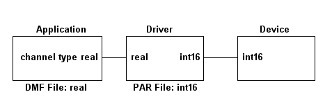
Example of the automatic type conversion between
real and int16 types Driver procedures
Driver
proceduresThe application may call for the driver certain
procedures using which it is possible to control the behavior of the
driver or to gain important information. This is done by means of the
system procedure: system.DriverQueryProc( DriverName : string; Param1 : any; &Param2 : any ) Parameters of the procedure have the following
meaning: | Parameter | Meaning |
|---|
| DriverName | symbolic name of the driver defined in the
application, | | Param1 | serves for typing of the command (name of the driver
procedure). | | Param2 | is used as a parameter of the procedure or the return value
of the procedure. |
DriverName and Param1 are typed as
text strings. Param2 is of various type according to the
meaning of the procedure. Some procedures serving for setting of
parameters may finish in error.
Overview and meaning of driver procedures (Param1 parameter)
- GetResult
-
Returns the result of the last called
driver procedure. The result is some of the error codes described in the
Chapter Error codes. This procedure should
be called after the calling of those procedures for which an error
occurred.
- GetVersion
-
Returns in Param2 the string
describing the driver name and its version.
- GetMajorVersion
-
Returns version higher word of
the product Control Web.
- GetMinorVersion
-
Returns version lower word of
the product Control Web.
- GetAPIMajorVersion
-
Returns version higher word
of the API product Control Web.
- GetAPIMinorVersion
-
Returns version lower word
of the API product Control Web.
- EnableException
-
By calling this procedure the
further driver exception is permitted.
- GetErrorCode
-
Returns the error number of the
just processed driver exception.
See chapter Error codes for
details.
- GetErrorString
-
Returns the error description of
the just processed driver exception.
- GetExcStatus
-
Returns the just processed driver
exception code.
See chapter Driver exceptions
and their handling for details.
- SetTraceOutput
-
Sets the target of trace outputs of the communication. The
parameter states the output target. | Value | Meaning |
|---|
| 0 | no trace outputs | | 1 | outputs are directed into the debug window of the Windows
system | | 2 | listings are directed into Log Windows of the tab
Debug outputs of the Control Websystem | | 3 | outputs are directed into the file
'\XTRACE.TXT' |
- SetBlockId
-
Sets the identifier of the current
block of channels for change of the address (offset) in the PLC memory.
The parameter is of the type string and the block
identifier is transferred in it (maximally 32 characters). This
identifier must be identical with the identifier in the definition of
blocks in the parameter file.
- SetBlockOffset
-
Sets the address (offset) of the
beginning of the block in the PLC memory. The block is determined by its
identifier in the parameter file and is selected by calling of the
procedure SetBlockId. The parameter can be of any numeric
type. Warning: The range of the parameter is not
monitored.
Driver map file and data types
DMF file contains types and directions for individual channels.
because the driver has a fixed set of maintenance channels and
also a variable set of data channels, the DMF file should always
contain part describing fixed set of channels and part describing
actually defined data channels corresponding to channels defined
in the [Channels] section in the parameter file.
| Data type |
Channel type |
Description |
| uint32 |
number |
32-bit unsigned value - 4 bytes |
| int32 |
number |
32-bit signed value - 4 bytes |
| float32 |
number |
32-bit real value - 4 bytes |
| float32s |
number |
32-bit real value - 4 bytes |
| |
| uint16 |
number |
16bit unsigned value - 2 bytes |
| int16 |
number |
16bit signed value - 2 bytes |
| |
| uint8 |
number |
8bit unsigned value - 1 byte |
| int8 |
number |
8bit signed value - 1 byte |
| bool8 |
boolean |
1 boolean value - 1 byte |
| bits |
boolean |
1-bit value - 8 in 1 byte |
| |
| sbit |
boolean |
1-bit value accessible for write |
Driver data types
Driver exceptions and their handling
The exception is raised when communication error appears. This
exception can be handled by any virtual instrument within the
application. The particular virtual instrument must define the
driver_exception parameter with the driver symbolic
name. In this case the instrument is activated when the exception
appears. It is necessary to write the true value to
the channel No. 2 or to invoke EnableException driver
procedure. This enables generation of next exception (if any). It
is possible to read channel No. 1 to obtain the exception state.
Keep on mind the send_same_data parameter must be set
to true if the instrument writes channel No. 2 (else
the next write of the same value will be discarded). If the
application does not handle exceptions, they are added to the
queue. Maximal queue length is defined by the parameter MaxExceptions
in the [Settings] section.
Exception status codes
0 - No exception. 1 - Exception signals data read error. Error
code and description can be obtained by GetErrorCode
driver procedure call or from the channel No. 6. 2 - Exception signals data write error.
Error code and description can be obtained by GetErrorCode
driver procedure call or from the channel No. 6. 3 - Data in device changed. This is the way
to signal data changed in the case of asynchronous
communication or if the driver works in the slave
mode. 4 - Driver procedure error. Because some
procedures can take rather long time to execute, they are
executed in the parallel thread not to block the
application. If the procedure ends with error, this
exception signals it.
Error codes
The driver generates several error codes. The code of actual
error can be read from the channel No. 6. Error code, together
with the error description, can be also obtained by calling GetErrorCode
and GetErrorString driver procedures. It the error
condition occurs then an error message is also written to Log
Window of the Control Web.
0 - success 1 - timeout error 2 - invalid value 3 - non-existing channel
1000 - internal error 1001 - checksum error 1002 - input communication buffer full 1003 - invalid device address 1004 - invalid function code 1005 - received data has invalid length 1006 - acknowledge error 1007 - invalid response 1020 - invalid procedure parameter 1021 - no data available 1022 - unknown driver procedure 1023 - unknown block identifier 1024 - invalid address (offset) within
block 1025 - device unplugged 1026 - data element read-only
Example of driver usage
There are several examples of the driver usage in the package
installation. These examples can be found in the
'EXAMPLES\S_MPI' directory. Examples also contain
'*.DMF' and '*.PAR' files. It is necessary
to modify these files according to actual device
configuration.
| 