| The driver allows Control Web to communicate
with arbitrary OPC server. The driver is compatible with OPC Data Access
v1 i v2 standards published by OPC Foundation.
Contents - OPC driver for Control Web
- What is OPC
- OPC versions
- Data transfer within OPC standard
- OPC name space
- Array data items
- OPC server initialization
- Remote servers and DCOM
- OPC driver configuration files
- Parameter file
- Section [server]
- Section [channels]
- Parameter file example
- DMF file example
- OPC driver configuration tool
- Choosing the OPC server
- Choosing channels
- Assigning channel numbers
- Assigning channel numbers to arrays
- Driver parameters
- Generation of configuration files
- Loading of existing parameter file
What is OPC
OLE for Process Control (OPC) represents the first successful
movement standardizing communication interface among various
industrial automation devices (PLCs, I/O devices etc.) and SCADA,
HMI and control computers. The OPC standard is valuable mainly for
customers, who no longer depend on proprietary protocols and
communication infrastructure of the particular supplier
(especially if such companies bar third parties from
implementation of their protocols by law barriers). The OPC
standard is maintained by non-profit OPC Foundation
(http://www.opcfoundation.org/) and OPC standard can be
implemented by anybody without royalty fees.
OPC is implemented as a software layer between industrial
automation devices and software, which exchange data with such
hardware. Hardware devices equipped by OPC servers are as easily
usable as e.g. new PC graphics adapters supplied with
driver — just plug it into the computer,
install driver and it works. Similarly, If there is a suitable OPC
server for some PLC, OPC clients should be able to exchange data
this PLC.
The OPC standard is based on COM — software component technology developed by Microsoft
Corp. The OPC abbreviation suggests using of OLE (Object Linking
and Embedding) technology, build above the COM foundation. But it
is rather difficult to distinguish what part is pure COM and what
is OLE, especially when Microsoft marketing department adds new
naming, like Active X. Because Microsoft itself uses COM in
various parts of Windows operating system, the COM is widely
supported and developed and contains number of features very
useful also for OPC, like system-wide component registration
(every OPC client can easily search for all installed OPC
servers), standardized data exchange formats, event and
notification interfaces etc.
The OPC standard is relatively complex and its various parts
cover various areas of industrial automation. The very basic is
the “OPC Data Access” standard, which is also used by the
OPC Client driver for Control Web.
OPC versions
The OPC standard evolves with the growing experience with its
usage. There are two main versions of OPC Data Access — version 1 and version 2. Due to the fact that COM is
based on individual independent interfaces (groups of methods
manipulating individual components), some interfaces of version 1
were preserved also in version 2. Other interfaces were removed
and replaced by new ones and there are also newly added interfaces
in version 2.
One of the COM technology advantage is that every client can
easily determine the version of the OPC server and to use only the
interfaces defined by the particulr OPC standard version. So some
clients can be able to work with both version 1 and version 2
servers. On the other side, due to interface based API of COM
components, the server can implement all interfaces defined by
both OPC versions and thus be able to work with all clients.
The OPC standard clearly defines, which interfaces are
required, and which are optional in the particular OPC version.
The OPC server implementation, which does not support some
interface required by OPC standard, is simply wrong
implementation. This does not mean the server cannot run at
all — clients not asking for unimplemented
interfaces can work with such server without problems. But if some
client ask for the missing interface, the wrong server
implementation surfaces.
Control Web OPC Client driver can work with
both OPC version 1 and version 2 servers.
Data transfer within OPC standard
The OPC standard defines number of ways to communicate
with clients to satisfy their needs:
Synchronous communication always waiting for data
transfer from/to the device. Synchronous communication with the server cache
only. Asynchronous communication always waiting for data
transfer from/to the device. Periodical communication of the server with the device
and callback to client when data changes.
The second and the fourth point demand the server to exchange
data with the device periodically and to store read values to the
cache and, if required, notify the client (using connection point
interface) that data was changed.
Although the OPC Client driver for Control Web
works with both version 1 and version 2 servers, it uses only
synchronous transfer with version 1. Asynchronous transfer defined
in OPC Data Access version 1 suffered from number of
problems — this is why the asynchronous
transfer based on the IDataObject interface was completely
abandoned in version 2 and replaced by the more effective
asynchronous communication using IConnectionPoint interface.
Usage of the synchronous communication does not negatively
involve the Control Web application execution.
The driver always works asynchronously from the Control Web point of view and does not block the application by
waiting to the finishing of data exchange.
The asynchronous communication is used with all OPC version 2
servers by default. But it is possible to force the OPC driver to
use the synchronous communication with the version 2 servers by
setting the sync parameter in the driver parameter file (see the
PAR file description for details).
The data communication defined by the OPC standard is much more
complex and is thoroughly described in “Data Access Custom
Interface Standard, Version 2”, published by the OPC
Foundation. But it is not necessary to understand the OPC data
exchange to effectively use the OPC driver for Control Web. The driver uses OPC features which fit the
Control Web driver requirements so the user can
use all features provided to Control Web, like
time stamps, quality of service etc., and let the driver to
translate them to OPC and back.
OPC name space
Every OPC server defines some name space, which assigns the
unique name to every data item, which can be communicated. The
name space can be flat (single level) or hierarchical (structured
to the tree with branches and leafs, similar to the folders and
files structure of computer disc drives).
The OPC server may (but is not required to) provide the
interface, which enables browsing of its name space. Such
interface is very beneficial, because every read or write to any
data item defined by the server requires adding of the particular
item to some client-defined group, which requires the knowledge of
the data item's name. If the name space browsing interface is not
provided by the server, the user (and the server vendor) must
define the way of item names specification.
The OPC standard does not presumes any rules for data item
names definition. The name can contain any characters, including
spaces, special symbols etc.
Array data items
Because OPC is based on COM technology, it utilizes COM
mechanisms to transfer data. But the COM allows definition of both
simple (scalar) values and also arrays of values in the VARIANT
structure. It depends on the particular OPC server if it presents
data as scalar data items or in arrays of items.
Although the possibility to define one array instead of
definition of every item separately, it also brings some
disadvantages — it is not possible to
transfer individual elements separately. Reading and/or writing of
only a few array items requires allocation of memory for the whole
array, copying of all array items to/from the memory and passing
of the array to COM layer. This is not a problem in the case of
small arrays, but it is necessary to count up with this overhead
in the case of big arrays with hundreds or thousands of items.
But transferring of whole arrays is not defined in the driver
interface of Control Web. The reason is the
inability to optimize data transfers and to communicate only
single values mentioned above. Regardless the Control Web enables definition of arrays on the application
level. What is defined as array of channels in the application,
particular driver sees like individual channels. Any continuous
block of channels (channels numbered by continuous number
sequence) can be defined as an array in the application. It then
depends on the driver how it optimizes communication of only some
elements, which need to be updated.
If the OPC driver access array data item on the OPC server, it
maps array elements to individual channels. If the array is
multidimensional, OPC driver (in compliance with COM definition)
increments the left-most index first. That means e.g. matrix is
stored in the column order (like in Visual Basic or FORTRAN
languages) and not in row order (like in Pascal or C/C++).
To enable mapping of array to individual channels, it is
necessary to number such channels by continuous number sequence.
Syntax of the PAR file, which defines individual channels,
enforces this rule.
Because arrays are mapped to individual channels by the driver,
it is possible to define array items as individual channels, as
one array, or as any combination of arrays and individual channels
within the application (it is even possible to define array, which
overlaps the boundary of OPC array and other items/arrays, if
channels are numbered sequentially). But the OPC driver must
communicate whole arrays only and it is strongly recommended to
mirror OPC server arrays to arrays in Control Web
application. The OPC driver configuration tool (describer later),
which generates PAR and DMF configuration files, follows this
rule.
OPC server initialization
OPC servers are rather complex programs, which have to perform
possibly time-consuming initialization during startup. Such
initialization can include scanning of the Windows Registry for
parameters, configuration file parsing, allocation of internal
data structures etc. Either way, not every server can accept user
requests immediately upon startup.
There is a method through which the server can return
its state, like “not configured”, “test mode” or
“running”. But different OPC servers return their state
different way. For instance there are servers, which return
state “running” immediately upon startup, even if they
are not prepared to accept client requests. The OPC driver
includes two ways to overcome such problems:
If the server returns state “not configured”, the
OPC driver can wait until the server state changes to
“running”. The second possibility is to simply wait for defined
period after the server is launched without respect to the
server state.
Either way, the OPC driver can start work with the server only
if it returns state “running”.
Remote servers and DCOM
Part of the COM technology is the ORPC (Object Remote Procedure
Call) extension called DCOM (Distributed COM). DCOM enables
clients running on one computer to create instances and invoke
methods of servers on another computer within the network. Because
DCOM was not available when Windows 95 was introduced to the
market, it is necessary to install free DCOM support to use it on
Windows 95. But modern operating systems (Windows 2000, Windows
XP) come with DCOM included.
OPC driver for Control Web supports DCOM, so
it is possible to create OPC servers on remote computers. All data
exchange over the network is then maintained by DCOM.
Because DCOM is the network technology, it is necessary to
configure it properly from the security point of view. Users
creating COM servers on remote computers must have granted access
to such computers. If there is a firewall protecting particular
networks from attacks and IP ports used by DCOM are blocked, the
network administrator should reconfigure firewalls to enable DCOM
network traffic. All such problems must be considered when
planning DCOM usage. Detailed description of computer and network
security can be found in Microsoft documentation.
OPC driver configuration files
As all Control Web drivers, the OPC driver
needs two configuration files to run — parameter file (.PAR) and driver map file (.DMF).
The purpose of both files is described in the Control Web
documentation. The DMF format is the same for all drivers and is
described in the Control Web documentation, it is
not necessary to describe it here.
The contents of both DMF and PAR files depends on the used OPC
server and defined channels. There is a GUI tool supplied with the
driver To simplify the configuration files creation. The users
need not to know the format of configuration files — they only select the server, mark items which should
be accessible as channels for Control Web
application and configuration files are generated automatically.
The OPC driver configuration tool is described in the second part
of this documentation.
However the knowledge of the OPC driver parameter file
structure can be useful e.g. when it is necessary to edit this
file by text editor of to generate it automatically by some other
program.
Parameter file
OPC driver parameter file follows the conventions of .INI
files, which are simple text files divided to individual sections.
Each section begins with line containing section name in square
brackets, followed by lines defining individual keys in the form
key_name=key_value. OPC driver requires two sections in parameter
file: [server] and [channels].
Section [server]
This section must contain the OPC server class identifier
— CLSID. Class Identifier is globally
unique identifier (GUID), a 128-bit number used in COM to
identify various objects, like classes, interfaces, type
libraries etc. The text representation of the GUID is defined
by COM and is used as key name in the Windows Registry folder
HKEY_CLASSES_ROOT\CLSID, where all COM components have to be
registered.
CLSID={F738C006-F632-4E9E-946E-2C2CF2A418A1}
If the OPC server should be created on remote computer
using DCOM, the parameter host must be defined. This parameter
contains UNC path to the remote computer (host), where the
required server is installed and where have to be run.
host=\\remotehost
As already noted above, OPC driver uses synchronous
communication with version 1 servers and asynchronous
communication with version 2 servers (only is the version 2
server does not support asynchronous communication interface,
synchronous communication is used).
While the asynchronous communication with version 1 servers
is not supported by the driver, it is possible to use
synchronous communication with version 2 servers by setting
sync parameter to true.
sync=true
If this parameter is missing or set to false, OPC driver
prefers asynchronous communication, if possible.
If the server returns its status “not configured”
(OPC_STATUS_NOCONFIG) upon startup and after finishing the
initialization returns status “running”
(OPC_STATUS_RUNNING), it is possible to wait for the
“running” state by setting the parameter wait_running
to true:
wait_running=true
If the server needs some time for initialization (and does
not reflect its state correctly), it is possible to insert
some wait period to driver initialization. Parameter wait_time
defines number of seconds of the waiting delay:
wait_time=2.5
Section [channels]
This section contains lines each defining one channel:
channel_number=identifier of the OPC server data item
If OPC data item identifies an array, there is a channel
number interval covering all elements of the array instead of
single channel number. The first and last channel numbers are
delimited by the '-' character (channel number cannot be
negative so the '-' character is not interpreted as negative
sign).
first_channel_number-last_channel_number=identifier of the OPC server array item
Because there are no restrictions on characters used in OPC
item identifier, all characters following the equal sigh up to
end of line are considered to be part of the identifier.
Channel definition needs no more information but data
identifier, because OPC server can provide all other necessary
attributes, like channel type, possible direction (read or
write) etc.
Parameter file example
[comment]
OPCDRV PAR file created by OPC Driver Configuration Tool
File: C:\BUFF\opc.par
Created on: 04/30/2002 16:31:21

[server]
CLSID={F8582CF2-88FB-11D0-B850-00C0F0104305}
host=\\remotehost

[channels]
100=Random.Int4
101=Random.String
102=Random.UInt4
103=Random.Real4
104=Random.Real8
105=Square Waves.Real8
106=Triangle Waves.Real8
107=Write Only.UInt1
108=Write Only.UInt2
109=Write Only.UInt4
110-119=Random.StringArray
120-129=Random.Real8Array
OPC driver itself requires only sections [server] a
[channels], other sections are ignored. The section [comment]
used in this example is ignored by the driver and servers ony
for storing of some additional information. The name of this
section is not relevant, any name other than server
and channels can be used.
DMF file example
The corresponding DMF file contents is shown for
illustration purposes:
OPCDRV DMF file created by OPC Driver Configuration Tool
File: C:\BUFF\opc.dmf
Created on: 04/30/2002 16:31:23
begin
   100 longint input
   101 string input
   102 longcard input
   103 shortreal input
   104 real input
   105 real bidirectional
   106 real bidirectional
   107 shortcard output
   108 cardinal output
   109 longcard output
   110 - 119 string input
   120 - 129 lonreal input
end.
OPC driver configuration tool
It is not very easy to get the CLSIDs of installed OPC servers
by browsing the Windows Registry and obtaining item identifiers,
their types and directions and typing PAR and DMF files in text
editor is event more complicated. This is why the OPC driver
configuration tool (OPCDRVCF.EXE) is supplied together with the
driver itself. This tool enables very simple selection from all
installed local or remote OPC servers, browsing of the selected
server name space and selecting which items should be visible as
channels to Control Web application and automatic
generation of PAR and DMF files. It is also possible to copy the
text definitions of appropriate Control Web
channels to the system clipboard so the text can be very easily
pasted to the application source code in the Control Web integrated development environment.
The configuration tool main window contains two panes — left pane shows a tree of the selected server name
space, right pane contains sheet with selected items.
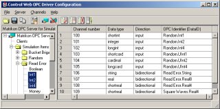
OPC driver configuration tool window Choosing the OPC server
First it is necessary to select the OPC server, with which
the driver should communicate. Menu Server/Connect to OPC
Server... opens a server selection
dialog.
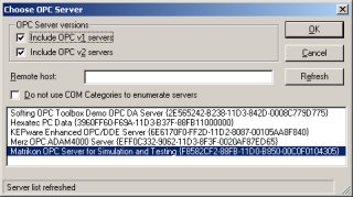
Choose OPC server window This dialog shows names and corresponding CLSIDs of all OPC
servers installed on local or remote computer. It is possible
to restrict the displayed OPC servers to version 1 or version
2 only. Many servers provide all interfaces of both versions
so they will be displayed in both cases. The OPC driver
configuration tool searches OPC servers according to COM
Component Categories, which is the standard COM component
identification mechanism. The OPC Foundation defined two
globally unique identifiers (GUIDs) for OPC DA Server v1 and
v2 categories. It is necessary to register particular category
and to assign appropriate category GUID to installed server
during installation process. But there are servers, whose
installation programs ignore this rule. This is why there is
the check box Do not use COM Categories to enumerate
servers in the dialog box. If the box is checked, the
presence of the OPC key in the Registry is used
for distinguishing OPC servers instead of COM categories. The
list of found servers then can contain components, which are
not OPC servers and an attempt to connect to such component
will lead to error message. On the other side, such option
enables to work even with wrongly installed server.
Choosing channels
If the server is successfully created, the left pane shows
its name space. Individual items can be added to the channel
list (the right pane) by double-clicking them or it is
possible to select more items at once and add all selected
items to the channel list using menu Channels/Append
selected items. Channel can be removed from the list
after selection of the whole channel line by clicking the box
on the left side of the line and pressing the <Del>
key or it is possible to use menu Channels/Delete
selected channel. It is also possible to clear the
channel list using menu Channels/Clear all
channels.
Some servers cannot provide valid information about their
name space immediately upon startup (and do not reflect this
state in the server status). This can cause the name space
tree appears not complete. Simply choose the same server
again, now the server is already running and the name space
tree should be complete.
The configuration tools tries to obtain information about
the data type (integer, string, etc.) and communication
direction (read, write, bi-directional) for each channel from
the server. Unfortunately there are some servers, which do not
provide such information at all or do not provide this
information for some items (e.g. items created as aliases to
other items). In such case, generated configuration files must
be edited manually.
Assigning channel numbers
Newly added channels have the channel number cell empty
(undefined). Channel numbers can be added individually for
each channel or can be assigned for all channels using menu
Channels/Renumber channels. Renumbering can affect
only channels with undefined numbers or can update numbers of
all defined channels.
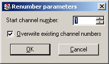
Renumber channels window Assigning channel numbers to arrays
Because items of OPC array are mapped to individual
channels, their numbers must be continuous sequence. This is
why only the first channel number has to be entered in the
configuration tools. Following array elements are numbered
sequentially.
Channel numbers must be unique, which is true also for all
elements of arrays. If there are for instance defined channels
number 1, 4 and 7, then to the elements of the array
containing three items can be assigned no lower numbers than
8, 9 and 10. Do not be confused by the error message
“Channel number redefined” — such
message can be caused by insufficient number of free channel
numbers for the whole array, even if the entered number (the
number of the first element) is not used.
The automatic channel numbering mechanism always assigns
unique numbers to single items as well as to arrays. If you
use automatic renumbering and there are some channels or
arrays with already assigned numbers, newly assigned numbers
for different channels and/or different arrays may by not be i
continuous sequence (elements of one array will be numbered
continuously, of course).
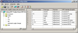
Channel array Driver parameters
It is possible to open a dialog window for specifying of
the driver parameters using menu File/Set driver
parameters... Parameters include
usage of synchronous communication, waiting for
“running” state and startup delay.
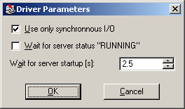
Driver parameters window Generation of configuration files
If all channels have assigned numbers, it is possible to
generate parameter (.PAR) and driver mapping (.DMF) files
using menu File/Write PAR and DMF files...
The menu command File/Copy channels to clipboard
can be used to put the text definition of channels (part of
the Control Web application source code) to
the Windows clipboard. The copied text can be pasted to the
text editor of the Control Web integrated
development environment and possibly modify channel names and
other attributes.
Loading of existing parameter file
Menu command File/Open existing PAR enables
opening of some existing parameter file to the configuration
tool. This command disconnects currently selected OPC server
(if one is selected) and clears all channels defined. Then the
server defined in the opened PAR file is created and the
channel list is filled by channels defined in the PAR
file.
Because the OPC server may not support all channels defined
within opened PAR file, the configuration tool checks if such
channels (OPC data identifiers) are available on the server.
It the OPC server does not provide some channel(s), the
configuration tool displays the corresponding line(s) with red
color and these item will not be included into newly generated
DMF and PAR files.
| 