|
Unlike other areas of industrial automation, the particularity of
machine vision applications is high number of unsuccessful solutions.
Despite all the profession advances, the design of machine vision is
relatively very difficult to understand and respect the basic
principles of imaging and work with image data. The most important is
the first phase of the proposal, that means determination the
geometric arrangement of the inspection system, camera choice, lens,
illumination and selection of appropriate hardware and software for
image processing. If you make a major mistake here, the probability of
failure is very high.
We must make the most important decisions first. The issue is quite
extensive and this article may include only a tiny fraction.
General task configuration
Choice of spatial configuration relatively determines the type and
number of cameras and illuminating units and the requirements on the
lens focal length. We must be sure, from what direction and distance
will the camera capture the scene, we must also set sufficient cameras
resolution, possibly need to use multiple cameras. It is needed to
decide about the way of illuminating and its color at the same time –
this is connected with the elimination of distractive light and
therefore the shading proposal and the possible need to use color or
polarizing filters in the camera.
Hardware and software image processing
Here we have a choice between two concepts:
Use of so-called smart cameras and image processing within
the capabilities of these cameras Connecting the cameras to the computer and image processing
by standard computer
An essential factor here is surprisingly not the cost of final
solution – both concepts are about equally expensive. Especially
important is the requirement on computing performance, flexibility and
variability of software. Smart cameras do image processing themselves
and are externally equipped with binary outputs, enabling to signalize
the result of the process. Usually do not allow free programming, it
is only possible to configure them through serial line or Ethernet
connection. They are usually equipped with specialized signal
processors or low consumption RISC processors with tact in hundreds of
MHz and simple real-time operating systems. These facts already
point to their limitations. Smart cameras are equipped with only a few
basic tools for image processing and are suitable only for simple
tasks. On the other hand, many tasks are usually dealt with
surprisingly simple means, and here the integrated cameras suit.
Estimate the situation in advance requires a lot of knowledge, sense
and experience. Where it is necessary to cope with such variable
scene, responding to changes in positions and shapes of objects,
lighting changes or to solve complex and performance-intensive
algorithms, we quickly run into limits that are firm and
insurmountable. Effort to solve by smart cameras tasks beyond their
means, is the reason for many failed projects.
Connecting the camera to a standard PC is a necessary choice for
complex applications, but also for simpler applications leaves us more
room to correct any inaccuracies in the initial estimate of
requirements. Performance of modern processors dramatically exceed
even the best smart cameras and embedded computer does not have to
take the form of a large box with several fans. In addition, many
typical operations with the image data can be accelerated by parallel
processing on multiple cores simultaneously. Some software systems,
and the spearhead of these technologies is e.g. VisionLab machine
vision system, can exploit the massive parallel performance of current
graphics processors. While today's CPUs have up to four cores, GPUs
divide the calculation e.g. to 240 cores. Such a system is capable
with image in real-time to perform until recently unthinkable
operations.
Even with more than adequate programming environment we sometimes
encounter the absence of the required functions or its poor
performance. The possibility of adding custom code can give us peace.
And even if it did not help to meet our requirements, at worst, we can
change the entire software system for machine vision and avoid failure
in dealing with contract. More room for operating is always handy.
In many cases it is sufficient when the only output in visual
inspection system is a binary output, signalizing a faulty product,
more often machine vision systems do not operate separately from the
rest of the world, but is required their integration into enterprise
information systems.The programming environment should allow the
inclusion of a visual inspection into wider context of operating and
visualization system, should transfer all data network, including
image data, communicate with the PLC, cooperate with SQL servers, HTTP
servers etc.
Further, suppose we propose a system where the cameras are
connected to a standard PC. It remains to choose the right camera,
lens and illumination.
Camera
There are so many criteria for selecting the camera, we can
consider the CCD or CMOS detector, chip size and resolution,
monochrome or color sensor. In the case of the color sensor may be a
single-chip implementation, three-chip color design or sequential
shooting with black and white sensor and color filters. Camera
connection may be analog or digital. In the case of a digital
interface we have a choice of Ethernet / IP, USB or Firewire. Digital
cameras can be run either with a fixed frame rate, can be externally
triggered, can run free with the accumulation of light, may provide
variously compressed data stream or can provide unbiased raw data,
etc. – when selecting the camera, really confusing number of criteria
plays the role.
Let's simplify the selection for the purposes of machine
vision. Above all, we must choose the appropriate point resolution –
for the purposes of measurements in image the resolution determines
the size of the measured object and demand for its measurement
accuracy. One pixel must theoretically correspond to the measurement
accuracy. This theoretical accuracy and reproducibility of measurement
is reduced by the effect of noise and unwanted image artifacts,
necessarily occurring in the lossy compression of image data.
Sometimes we can use statistical methods to reach the Sub-pixel
measurement accuracy, and generally without the knowledge of things
but it is not possible to design a system like this. In the case of
single-chip color cameras has to be taken into account approximately
half the linear resolution ability. In color mosaic, usually from four
pixels, two pixels are green, one red and one blue. This brings not
only the lower resolution ability, but also as e.g. image cross-shift
in different color channels.
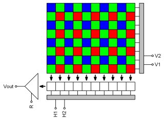
Arrangement of color mosaic on CCD chip In addition to resolution, we must choose connection and type of
camera. We probably reject an analog camera for machine vision needs.
Digital cameras are usually connected at a bigger distance via
Ethernet and at a short distance through the USB. The principle of
cameras digital connection itself is not the guarantee of image
quality. The cameras are generally designed very similarly - the vast
majority of digital CCD camera includes similar integrated camera
controller, that digitizes data from the CCD, balances color,
interpolates colors from the Bayer mosaic and lossy
compresses data to MJPEG or MPEG4 stream. Considering the
compromisingly reduced characteristics of integrated image processor,
the quality of these operations is always visibly limited and the
resulting image is so burdened with significant undesirable artifacts.
Therefore, already at the stage of conceptual design of machine vision
we must have a very precise idea of what image quality we need.
Purity, stability and accuracy of image certainly is not essential for
all types of applications, sometimes it is surprising that visual
inspection works based on the presence or absence of a few blurry
spots in the pre-defined positions. But for more complex applications
it is the image quality what makes stable and therefore successful
operation of inspection system decisive. Best image quality achievable
bring cameras, which provide RAW image data. The image is not
transformed by these cameras, color balanced, interpolated nor
compressed. It delivers unmatched image precision, which is available
in the connected computer, and there can be processed without any
compromises limiting its quality. High bitrate can be sometimes an
obstacle between the camera and computer. In short-distance
connections these requirements are perfectly solved by the USB 2.0
interface with bitrate up to 480 Mb/s (one cable at 5 meters and
up to 30 meters when using active extension and hub).
Lens
Choice of lens and visual angle is on of the most important
decisions in designing a machine vision system. Common types of lenses
reflect the image into area with so-called perspective projection.
This compels us to deal with features of projective imaging of
three-dimensional scene into two-dimensional area of image sensor's
surface. Lens field of view is in this case formed by viewing
truncated cone. Rectangular area of the image sensor further reduces
this cone into viewing pyramid. Its peak is called the focal point of
the projection. When converting a scene image inside viewing pyramid
into image area, there is considerable loss of information. Each
half-line passing through the focal point of the projection is in the
image area represented by a single point.
Even the theoretical assumption of a perfect lens with linear
transfer from angle to position and planar two-dimensional scanning of
the pattern, we have to deal with distortions of image geometry due to
perspective errors. Imagine a picture of dark dots on a light
background with a constant spacing of dots in the axes x and y. To
achieve a constant spacing of dots provided accurate perspective
projection even in the projected image, the pattern must be scanned
from the inner surface of the spherical area. When the planar pattern
spots in the projected image will move away from each other depending
on their distance from the optical axis.
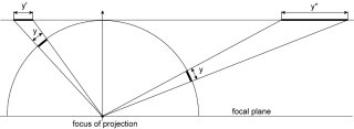
Distortion of the geometry of planar image in perspective
projection Loss of spatial information in perspective projection complicates
e.g. the exact measurements of sizes of three-dimensional objects.
Without prior knowledge of taken subjects shapes we are not
additionally able to correct these errors. Even with knowledge of the
object's shapes, the correction of projective errors requires
identification of objects of machine vision software equipment,
therefore a high level of image understanding is required. In addition
to normal lens with a perspective projection, there are also special
lenses with orthographic projection. These lenses do not display a
scene with a focal perspective, but with a perpendicular parallel
projection. So, the size of the displayed items are always the same,
regardless of their distance. That sounds like a good solution to all
problems with accurate measurements in the image, but it has one
problem. In this type of projection the size of the lens input
surfaces must be similar to the area of scanned scene. These so-called
telecentric lens are then very large and expensive. The principle of
telecentric lenses is quite simple. With aperture diaphragm located in
plane of image main point (outbreak lenses) all the rays coming from
other directions than parallel to the optical axis are blocked.
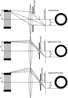
The projection principle of normal, telecentric and
hypercentric lens In order not to end all problems, significant limitations of
measurement accuracy in the image can cause the geometric distortion
of image field of lenses, and they occur even at telecentric lenses.
By distortion we mean the difference between the theoretical position
of a pixel, which derives from the principle of projection and the
actual position of point displayed by an actual lens. At the actual
lenses there is never a transfer between the angle position (or
distance) of an object from the optical axis and between the image
distance of the object in the image area completely linear. Angle
transformation at distance has quadratic character, but more often,
the cubic polynomial. When using with several-megapixel cameras, even
a very good lens has usually radial distortion in the range of units
to tens of pixels. In some applications, such as when we read texts,
codes or count components, it does not have to matter. In applications
where is the required precision of measurements, the lens quality
becomes a crucial factor.

The usual geometric distortion of image field While with the principles of projection we cannot do anything,
distortion of image field can be corrected by software and we can
achieve outstanding sub-pixel accuracy with standard lenses. The
problem may be computational complexity of correcting algorithms. For
example, VisionLab system carries out these corrections using the GPU
with quite minimal impact on computers workloads.
Lighting
While in the preceding paragraphs it is possible to estimate the
right solution intellectually very well in advance, and often to
accurately calculate, the correct choice of lighting requires
considerable experience and often a lot of experimentation. Especially
if the scene consists of transparent, shiny or embossed unremarkable
objects, lighting design is the key of overall success. We must choose
the type, number and position of lighting units and the color of their
light. Often it is necessary to solve blocking an unwanted light from
the surroundings by shading and color filters in the camera. The
polarizing filters can contribute to a significant reduction of
unwanted reflections .
Cheap lighting can be solved e.g. by using fluorescent tubes,
possibly even without electronic ballasts, but the camera must be able
of sufficiently long exposure times. More quality and better
parameterizable lighting provide light-emitting diode units, whose
price has been reduced so much that is usually not an obstacle to
deploy them. If operating the lighting during the activity is needed,
e.g. setting brightness, colors or initialize flashes, it is a great
advantage to have an option of operating the lighting units directly
from cameras.
In conclusion
If we did not leave anything substantial in the previous steps, it
remains only to choose appropriate software for image processing and
understanding (and of course everything to configure and program) and
the success of the contract should no longer be endangered.
DataCam digital industrial camera offer interesting properties for
use in machine vision systems. It is a low-noise CCD cameras, which
provide clean raw image data in sixteen bit dynamic pixel brightness.
Are connected to a computer via USB cable, from which are
simultaneously powered. Cameras excel in image quality and
clarity.
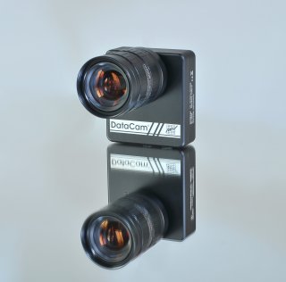
DataCam digital camera Each of these cameras can directly control up to four DataLight
lighting units, which are available in the form of a circular
illuminators, area illuminators, flash illuminators and illuminated
panels. At DataLight units, we can choose color and emissive angle of
diodes and possibly the presence and type of diffuser.
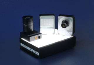
DataLight lighting units with DataCam camera At the top of the pyramid schemes of components for machine
vision stands software, which is able to understand images. Richly
featured VisionLab system aims to facilitate the creation of most
machine vision applications and easy integration of applications
into the IT organization. Its advantages include:
easy integration of digital images and visual inspection for
applications in industrial automation intuitive steps editing of machine vision chain support of fully parallel processing on multiple cores and
multiple CPUs support of massively parallel image processing by
GPU advanced image adjustment by GPU 
Morphological image transformation can be implemented
on the GPU using the data stream from the cameras in real
time image data transmission in computer networks image data archiving in the form of images and video open interface for adding steps for machine vision sharing data with the applications of the Control
Web system
RC
| 