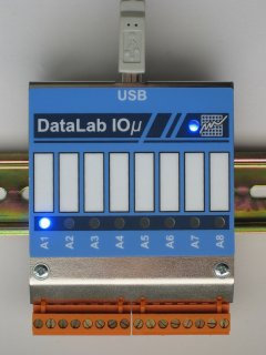
CPU module for DataLab IF/EIB
System processor unit DataLab 1 slot for the EIB I/O module USB connection Optional assembly on DIN bar |
 |
| The unit is delivered only as a whole with the
interface module DL-IF/EIB. |
Dimensions
Indication of terminals
I/O modules
It is possible to mount the unit with one DL-IF/EIB I/O
module. The module is connected to the CPU board through a
connector. After mounting of the upper cover the module is
mechanically fixed in its position.
Other modules of the DataLab
system cannot be connected to this unit.
Handling of the I/O module
The unit is delivered mounted, including the connected
DL-IF/EIB module. Since the unit does not make it possible to
connect another module, it is not necessary to handle the I/O
module in another manner.
| Removing the module | Access to the module is gained after removing the
upper cover of the unit. Lift the side with the connecting
connector upwards by about 2 mm
and remove the module by drawing from the CPU
board. | | Insertion of the module | Insert the module into the connector of the selected
slot of the CPU board. After end-to-end insertion the edge
of the module board fits behind the edge of the box. After
mounting of the upper cover the module is mechanically fixed
in its position. |
Ordering codes
| DataLab IF/EIB |
Interface USB/EIB (DL-CPM/EIB +
DL-IF/EIB) on DIN bar |
| DataLab IF/EIB
S |
Interface USB/EIB (DL-CPM/EIB +
DL-IF/EIB) desktop variant |
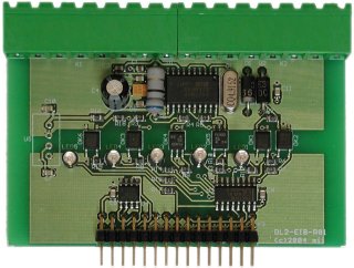
EIB interface module
System module DataLab Independent supply of the EIB and USB
part Galvanic separation of the EIB and USB
part Throughput terminal board for easy
connection Indication of failure status |
 |
The module is delivered only as a whole with
the processor module. |
For connection of conductors the connector terminal board is
used. This solution simplifies connection of signals and
commissioning of control applications.
The DL-IF/EIB module contains a galvanically separated
interface for the EIB busbar resolved by means of ASIC Siemens
TP-UART. The module displays the hardware status by means of LED
indicators.
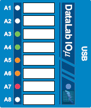
Indication and meaning of terminals and LED
| A 4.1 | EIB + | | A 4.2 | EIB – | | A 5.1 | EIB + | | A 5.2 | EIB – |
|
|
 |
|
|
|
 |
|
|
| |
| transmission into EIB (negated) |
| receipt from EIP |
| indication of RESET of the interface |
| under-voltage in the EIB network |
| exceeded chip temperature |
ON |
| |
Parameters of the module
The parameters of the module fulfil conditions for EIB
devices connected to the TP medium.
| EIB Uin |
DC 30 V (21 V–32 V) |
| EIB Imax. |
1,6 mA |
Ordering codes
| DataLab IF/EIB |
Interface USB/EIB (DL-CPM/EIB +
DL-IF/EIB) on DIN bar |
| DataLab IF/EIB
S |
Interface USB/EIB (DL-CPM/EIB +
DL-IF/EIB) desktop variant |
| 