|
The DataLab IO units are not sold in some
predefined configurations. Every customer can specify which modules
should be included into the device. Modules can be digital or analog
and input or output. There can be several kinds of one module
class—for instance there are two kinds of
digital output module, one with open-collector transistors, another
with relays.
All I/O modules are universal—they can
be used in any slot of any DataLab IO
device—DataLab IO4,
DataLab IO2 and DataLab IO1.
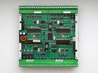
The DataLab IO4 with four
I/O modules 
The DataLab IO2 with two
I/O modules 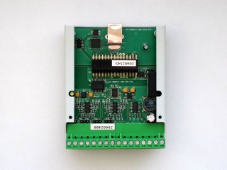
The DataLab IO1 with one
I/O module Analog input module AI3
This module is designed for measuring of analog voltage or
current values in the standard industrial ranges with 16-bit
resolution. Inputs are bipolar and electrically isolated.
| Range |
Voltage input |
Current input |
| 0 |
input inactive |
input inactive |
| 1 |
+/-10 V |
N/A |
| 2 |
+/-5 V |
N/A |
| 3 |
+/-2 V |
+/-20 mA |
| 4 |
+/-1 V |
+/-10 mA |
| 5 |
+/-0.5 V |
+/-5 mA |
| 6 |
+/-0.2 V |
+/-2 mA |
| 7 |
+/-0.1 V |
+/-1 mA |
| 8 |
input inactive |
input inactive |
| 9 |
0..10 V |
N/A |
| 10 |
0..5 V |
N/A |
| 11 |
0..2 V |
0..20 mA |
| 12 |
0..1 V |
0..10 mA |
| 13 |
0..0.5 V |
0..5 mA |
| 14 |
0..0.2 V |
0..2 mA |
| 15 |
0..0.1 V |
0..1 mA |
Input ranges of AI3 analog input module The default input range is +/-10 V.
There is a jumper on the module PCB associated with every input
channel. Closing the jumper causes a precision 100 Ω
resistor is inserted into the input, which changes voltage input
into the current one.
Input ranges can be defined for every input channel
independently by the application program. But the voltage or
current mode is selected by jumper on the PCB and this cannot be
performed on application runtime.
The AI3 module allows not only input range setting for
individual inputs, but also allows switching each input off.
Skipping of particular input speeds up the sampling frequency of
remaining inputs.
The module is able to sample data at frequency 50 Hz (50 samples per second) on one channel. If
all 8 channels are measured, the sampling speed is
6.25 Hz. If it is
for instance necessary to sample data 10× per second, only 5 channels can be turned on,
remaining 3 channels must be turned off.
It is not necessary to wait for the digital filter to settle
down when only one channel is measured and the input multiplexer
is not switched. The data sampling frequency is then 200 Hz. But keep on mind that the A/D converter is
not able to pass the step over the full input range to its output
at this speed. If the input voltage changes e.g. from
-10 V to +10 V, the converter needs 4 cycles to propagate
the step to the output. So the sampling frequency is again
50 Hz.
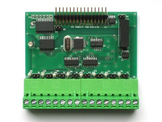
Isolated 16-bit analog input module Analog output module AO1
Analog output module provides 8 voltage analog outputs with the
range 0 to +10 V. D/A converter has
12 bit resolution. Each D/A converter
count equals to 2.5 mV output voltage
change.
Because 12 bit resolution provides 4096 counts,
2.5 mV per count equals
10.24 V. If the output must not exceed
10 V, the software must not write value greater than 4000 to
the output channel.
When the driver is configured to use physical units (volts),
such problem does not occur. For instance writing 10 to the output
channel means the 10 V (with the
uncertainty about 0.1 % caused by used components) appears on the
output pins.
First four of eight outputs can be configured as current
outputs with range from 0 to 20 mA using jumpers on the
module PCB. Due to the high resolution of the DAC the 4 to
20 mA range is implemented by software limitation of 0 to
20 mA range.
The current source generates 20 mA
when the DAC value is 3846 counts (with the uncertainty about
0.1 % caused by used
components). Configuring the driver to use physical units
(amperes) eliminates the necessity to recalculate written values.
For instance writing 0.02 to the output channel
means the current source will generate 20 mA current.
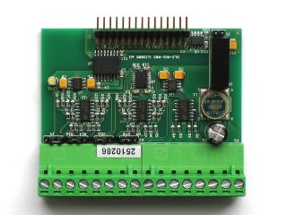
Isolated 12-bit analog output module Combined analog input and digital input/output module
AD1
The AD1 module provides four differential analog inputs,
functionally equivalent to the AI3 module.
| Range |
Voltage input |
Current input |
| 0 |
input inactive |
input inactive |
| 1 |
+/-10 V |
N/A |
| 2 |
+/-5 V |
N/A |
| 3 |
+/-2 V |
+/-20 mA |
| 4 |
+/-1 V |
+/-10 mA |
| 5 |
+/-0.5 V |
+/-5 mA |
| 6 |
+/-0.2 V |
+/-2 mA |
| 7 |
+/-0.1 V |
+/-1 mA |
| 8 |
input inactive |
input inactive |
| 9 |
0..10 V |
N/A |
| 10 |
0..5 V |
N/A |
| 11 |
0..2 V |
0..20 mA |
| 12 |
0..1 V |
0..10 mA |
| 13 |
0..0.5 V |
0..5 mA |
| 14 |
0..0.2 V |
0..2 mA |
| 15 |
0..0.1 V |
0..1 mA |
Input ranges of AD1 analog inputs The default input range is +/-10 V.
There is a jumper on the module PCB associated with every input
channel. Closing the jumper causes a precision 100 Ω
resistor is inserted into the input, which changes voltage input
into the current one.
Input ranges can be defined for every input channel
independently by the application program. But the voltage or
current mode is selected by jumper on the PCB and this cannot be
performed on application runtime.
The AD1 module allows not only input range setting for
individual inputs, but also allows switching each input off.
Skipping of particular input speeds up the sampling frequency of
remaining inputs.
The module is able to sample data at frequency 50 Hz (50 samples per second) on one channel. If
all 8 channels are measured, the sampling speed is
12.5 Hz.
It is not necessary to wait for the digital filter to settle
down when only one channel is measured and the input multiplexer
is not switched. The data sampling frequency is then 200 Hz. But keep on mind that the A/D converter is
not able to pass the step over the full input range to its output
at this speed. If the input voltage changes e.g. from
-10 V to +10 V, the converter needs 4 cycles to propagate
the step to the output. So the sampling frequency is again
50 Hz.
The AD1 module also contains four digital input/output
channels. The module contains a set of jumpers on the PCB, which
allow choosing of channel direction (input or output) and channel
input resistance (low voltage or high voltage) for the input
direction. Every channel can be switched independently so the
actual number of inputs and outputs is chosen by the user.
Digital inputs are bipolar and they can be read in two
modes—DC and AC. Reading the channel in DC
mode returns the actual logical value according to the voltage
present on the terminal connector pins. AC inputs are evaluated
the same way like in the case of digital input modules.

Combined analog input and digital input/output
module Combined analog input/output and digital input/output module
AD2
The AD2 module contains 4 analog input channels, 2 analog
output channels and 2 digital channels, which can be configured
either for input or output.
The analog input part of the AD2 module is identical to the AD1
module. Refer to its description for input ranges, sampling
frequencies etc.
Two analog output channels of AD2 use 8-bit D/A converter.
Bout analog outputs can be independently set as voltage or current
using the PCB jumpers. Voltage range is 0 to +10 V, current range is 0 to 10 mA. Maximum
sampling rate 200 Hz is limited by the communication speed
between the DataLab IO device and the
host computer.
The AD2 module also contains two digital input/output channels.
The module contains a set of jumpers on the PCB, which allow
choosing of channel direction (input or output) and channel input
resistance (low voltage or high voltage) for the input direction.
Every channel can be switched independently so the actual number
of inputs and outputs is chosen by the user.
Digital inputs are bipolar and they can be read in two
modes—DC and AC. Reading the channel in DC
mode returns the actual logical value according to the voltage
present on the terminal connector pins. AC inputs are evaluated
the same way like in the case of digital input modules.
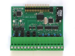
Combined analog input/output and digital input/output
module Analog input/output module AIO1
The AIO1 module combines two high-precision modules AI3 and
AO1. It contains 4 16-bit analog inputs and 4 12-bit analog
outputs.
The analog input part of the AIO1 module is identical to the
AD1 module (which is in fact just “one half” of the 8
channels AI3 analog input module). Refer to its description for
input ranges, sampling frequencies etc.
Analog output part is similarly identical to the “one
half” of the AO1 module. Refer to its description for output
modes, ranges, sampling frequencies etc. The only difference is
the AIO1 module contains only 4 analog outputs, so all 4 outputs
can be used both in voltage mode (with range from 0 to 10 V)
and in current mode (with range from 0 to 20 mA).
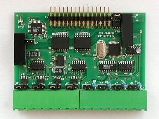
Analog input/output module Digital input module DI1
Module contains 8 insulated digital inputs. The module
is available in two variants for two input signal levels. The
DI1L variant is designed for 0 to 18 V input range, DI1H variant is designed for
0 to 35 V input
range. Voltage levels for DC signals for logical true and false
are:
DI1L parameters
Input resistance is 1 000 Ω 0 to 1 V is evaluated as false. 3 V to 18 V is evaluated as
true. The logical value is undefined for input voltages
from 1 V to 3 V. DI1H parameters
Input resistance is 4 700 Ω 0 to 3 V is evaluated as false. 8 V to 35 V is evaluated as
true. The logical value is undefined for input voltages
from 3 V to 8 V.
Timing limits for AC signals are:
Maximum sampling rate for DC signals is limited by USB
communication between DataLab IO and host
PC. The communication overhead is approx. 2ms1, which results to maximum frequency around
500 Hz. This frequency depends on used computer, its USB
interface and also on USB load factor—if
the unit is connected through USB hub together wit another USB
devices (e.g. USB disk drive), the maximum sampling rate can
significantly decrease. On the other side, the system response
does not depend on the number of communicated channels of one
module—the response time is the same if
the application manipulates only one or all eight channels.
Optical input decoupling is independent on input signal
polarity, which means the module can read also AC inputs.
Evaluation rules of logical values differ from DC mode, they are
thoroughly described in the DataLab IO driver
description.
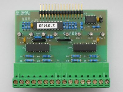
Optically insulated digital input module Single-ended digital input module DI2
This module is a functional equivalent of the digital input
module, including sampling rates, voltage levels etc. The only
difference is the common ground for all 8 inputs is wired to one
terminal connector. This module can contain insulated DC-DC
converter, which enables sampling of voltage-less inputs (simple
switches).
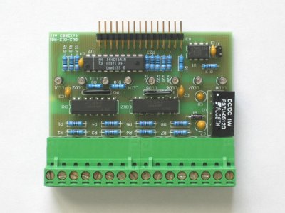
Optically insulated common-ground digital input module
with power supply Digital counter input module CNT1
The module contains 4 isolated digital
counters.
Counter range is 24-bit (0 to
16,777,215) 25 kHz maximal input
frequency with 1:1 duty cycle Two counters with alarm output signaling exceeding of the
predefined value Two counters with external counting enable (gate)
signal Counter modes (counting enable, logical signal levels
etc.) are defined by software
Limit frequency ensuring error-free counting if 25 kHz when the signal has 1:1 duty cycle. If the
duty cycle is not 1:1, limiting frequency is lower, because the
input signal must stay in each logical state for at last
20 μs. For
instance the limiting frequency is 10 kHz for the 1:4 duty cycle.
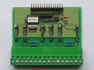
Digital counter module Incremental counter module CNT2
The module contains 1 incremental counter.
The module contains quadrature modulation
decoder Other counting modes include up/down and step/direction
counting Counter range is 32-bit (-2,147,483,648 to
2,147,483,647) 25 kHz maximal input
frequency with 1:1 duty cycle Two logical outputs signaling underflow and overflow of
defined values Logical input for counter value preset Logical input for counter value capture
Limit frequency ensuring error-free counting if 25 kHz when the signal has 1:1 duty cycle. If the
duty cycle is not 1:1, limiting frequency is lower, because the
input signal must stay in each logical state for at last
20 μs. For
instance the limiting frequency is 10 kHz for the 1:4 duty cycle.
Relay digital output module DO1
Module contains 8 relays with limit values:
Maximal voltage 230 V AC, 3 A. Maximal voltage 30 V DC, 3 A.
Estimated relay life (mechanical) is 100 000 switches and
life (electrical) is 20 000 000 switches. Maximal
frequency depends on the relays and exceeds 50 Hz.
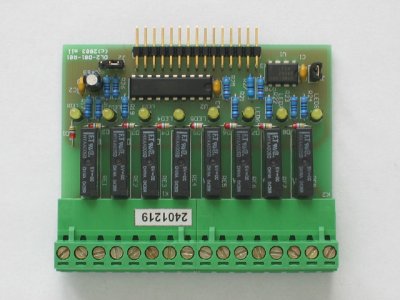
Relay digital output module Open-collector digital output module DO2
Module contains 8 insulated digital outputs. Limit
levels are:
Sampling frequency is limited as in the case of digital input
module.
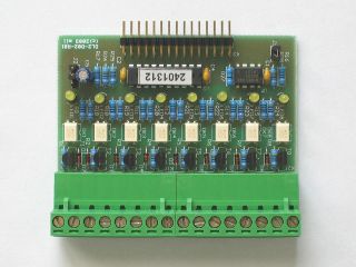
Optically insulated open-collector digital output
module Single-ended open-collector digital output module DO3
This module contains 8 digital outputs witch
open-collector transistors. All outputs have common ground.
Limit levels are:
Sampling frequency is limited as in the case of digital input
module.
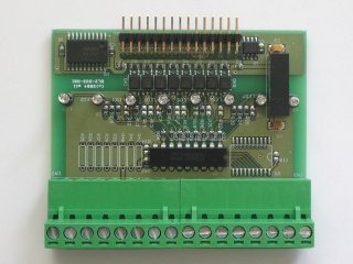
Single-ended open-collector digital output
module
1Measured on
the Athlon XP 2000+ PC with VIA KT 400 chipset and Windows XP
Professional
| 